Friday, October 10, 2008

There's only one way to build. UP!!!!

Today, I finished wiring in an NCE Booster, NCE EB3 three zone circuit breaker and a DCC Specialties Auto-reverser for the CAGY reverse loop and another for the lower level wye. All is working well. I've still got to get the command station set in it's permanent home. I want to build a shelf under the layout for it along with a pull out desk for a laptop computer so that I can connect to the command station and run Decoder Pro. Hope to have this in next week. 

In the mean time, I've started on the upper deck benchwork. I debated and debated on what I would use to support the upper deck. Finally, I decided on using 1/8" think angle iron. I've got the first section up and it's quite sturdy. I like this method as it does not interfere with where the back drop will go later.  I attached the angle iron with 5 screws directly to the stud walls. This is very sturdy. No, it's not "I can sit on it sturdy but I believe my 3 year old daughter could and I don't have all the iron in yet. I'll post more as the benchwork moves along.

Wednesday, October 8, 2008

A few pics from the layout

Once I got the main complete, I decided to run some trains and play. Here are a few photos from the fun. 

This is a shot of an IC local with 9145 in the lead. I backed it onto NS main #2 in Meridian. Notice how the track kinks out for more spacing between the mains at the end of the local. The extra spacing will be for the passenger platform in Meridian. 

Here, the 9145 is overtaken by another local out of Artesia led by IC 9042.  

IC 9145 speeds by the camera on it's local run.

THE lower GOLDEN SPIKE!!!!

The lower level main line is COMPLETE!!! I can now run a train around the entire room. 

The golden spike was driven on the lift-up section of the layout which works smoothly but slightly heavy. The heavy part comes in handy though when in the down position by reducing any possible movement from a bump. To ensure that the rails don't move, I screwed some 1" brass screws under the rails on each side of the gap and soldiered the rails to the screws. All is solid and trains run smoothly across. Here two locals meet nose to nose for the Golden Spike Ceremony!!! 


I've also done a little work on the Meridian yard. This is a view looking "East" from the Meridian yard. I've freelanced a bit here. You can see the ICG/MidSouth/KSC main coming around the curve in the background. The double track crossing is the NS crossing on the East end of Meridian. The ICG can either cross the NS to enter the Meridian yard or hit the turnout to get onto the NS main around the yard to connect back with the ICG and on to Vicksburg. 


This is looking "West" from the NS crossing into Meridian. At the far end of the yard is the lift-up section with a train crossing. My next project is to get the lower level DCC power districts set and get my two boosters wired in. I'm still waiting on track from Micro Engineering so after the DCC wiring, I'm going to tackle the upper deck benchwork. My goal is to have the upper level benchwork in by Christmas.

Friday, September 12, 2008

Spanning Tibbee

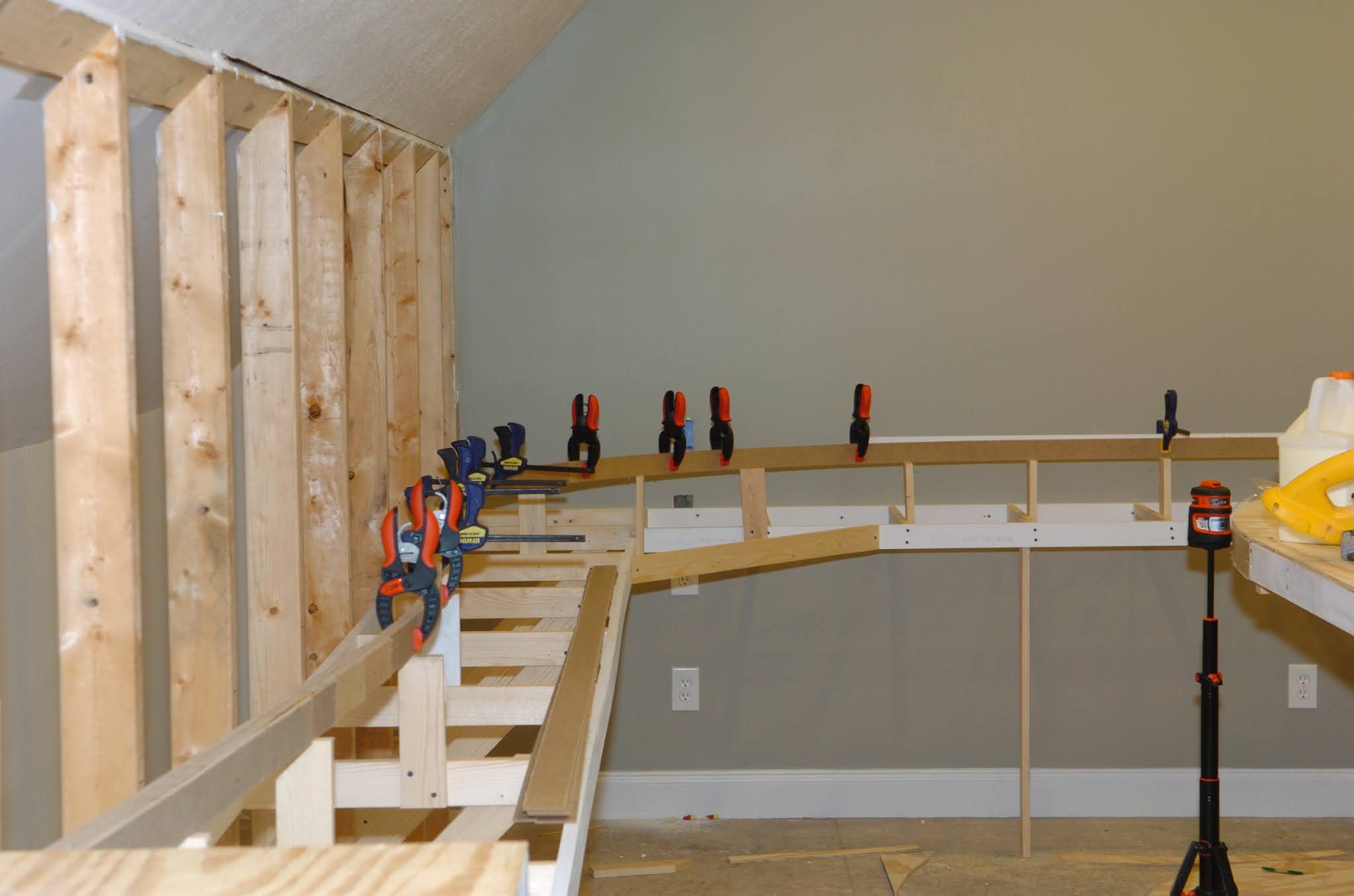
I've run out of track and am waiting on Micro Engineering to make more. Hope to have some next week so I can finish the lower deck main. In the mean time, I've been working on the bridge across Tibbee Creek. Here is the real deal again for reference. 


So far, I've completed construction of the Central Valley 150' Pratt Truss Bridge. As you can see, this bridge kit is a great fit for the prototype. This is actually two Central Valley kits bashed into one. Notice on the South (right) end of the bridge, there is a steel deck approach. I had to use the decking from a second CV kit to build this. I also did a few minor changed to the truss as opposed to what the CV instructions said. Over all, it was a fun kit to build. Now for a little sanding, primer and paint. 

The concrete section on the North (left) end has also been a treat to build. I had planned on scratch building this section until someone saw this blog and pointed me to The Scale Segmental Bridge Co. , www.scalebridge.com . They had a kit that was a dead match for this concrete span and it's been a delight dealing with that company. I have to admit that I've had about the best overall kit building experience with this kit than any other kit I've ever constructed from ordering, company support, packaging and to the actual building of the kit itself. A+ product. You'll see more of their bridges on my layout as I move forward. I'm sure we'll also see some exciting products from them in the future.

Thursday, September 11, 2008

The first run of the CAGY!!!!!

I'm rolling along pretty good. Today, I finished getting the reverse loop in around the helix. This loop will represent the Columbus and Greenville's track from West Point at Prestage Farms on West to Greenville. I put a curved switch in going around the loop that will lead to an expanded area that will actually be Greenville one day. 
 
Here, the CAGY makes it's first run to Greenville and back with some leased IC power. :)
The part that I enjoyed about his was the wiring portion. I'm using the NCE PH-PRO R system and a DCC Speciallists PSX-AR for the reverse loop. I wired all that in this morning. VERY simple and it works wonderfully.

Tuesday, September 9, 2008

Lift up section in place


Progress, progress, progress!!!! My original track plan included a helix at both ends of the layout. This would offer continuous run loops over the whole layout. The second helix was going to connect the Meridian yard to the Louisville yard. After getting the first helix in, I realized how much real estate these things eat up. I wanted to keep the middle of the room as open as possible for seating and such. So, back to the drawing board. In order to have continuous run capability, I was going to have to cross a doorway that led into my workshop and attic. I didn't want to cross this but finally decided to instead of the second helix. I toyed with several ideas including lift outs, swing outs, duck unders.....etc. I finally decided to give a lift up a try. I mounted some heavy duty 36" draw slides vertically on 2X4 supports. Now, the section lifts up like a draw bridge. So far, so good but I've yet to lay track across it and run a train. That will determine if I'm successful or not. Here you can see it in the lowered position and the raised position. It's held up by carriage bolts insterted into holes drilled into the 2X4s.  I hope to get some track layed across it soon. I'll report back when that's done and a train crosses...a few times. : ) 


Working on Tibbee Bridge

I've been working on building the bridge that will cross Tibbee Creek. It's been a fun project so far. 

Here is a shot of the Central Valley kit almost complete. I've still got a few parts to apply before it hits the paint booth. I went out yesterday to get a paint chip for a good match. Hope to get it painted soon. 

 In the mean time, I'm starting to gather materials to build the wooden approach trestle as seen here. I plan on building it out of scale lumber and am trying to find a good glue to use and a good stain that will match the creosote color of the bents. Any suggestions would be appreciated.

Saturday, August 23, 2008

working towards Artesia...

Track continues to get laid around the room. Here, I'm approaching the yard at Artesia. The crossover is in place and the wye switch is soon to be placed.


This is a view of the prototype. You can see the crossovers and yard beyond.


Another view of the Artesia yard. The crossovers are at the bottom on the photo.

The iron horse rolls...

I finally got enough track down to start rolling some trains. In the photos is a Proto 2000 IC GP9 with DCC and sound. I'm using an NCE Power Cab to run the layout at present but the Powerhouse Pro Radio is sitting in a box ready to be installed next week or so. That's tropical storm Fay knocking at the window.

This photo shows the CAGY to the Left and the track leading towards Tibbee Creek Bridge on the right.
 
This is the Tibbee Creek bridge. I hope to get started soon on the Central Valley Truss kit that is almost a perfect match. The rest of the bridge, concrete and trestle will be scratch built.

Laying the iron......

I started the track work as I built the helix. I did the helix track first then started the rest of the layout at the CAGY interchange.
In this photo, the Aberdeen Sub main is the track to the far right. The left three tracks are the Columbus & Greenville tracks at the Prestage Farms mill in West Point. The CAGY interchange is at the top of the photo. The real CAGY with Prestage farms can be seen here: http://maps.live.com/default.aspx?v=2&FORM=LMLTCC&cp=pkymn67m8wvf&style=b&lvl=2&tilt=-90&dir=0&alt=-1000&scene=13301879&phx=0&phy=0&phscl=1&encType=1
 
 
This was my first attempt at a bridge on the layout. It's a basic Walthers kit that I thought turned out well. This kit built as it is, is almost a perfect match for the trestles near the Tibbee Creek bridge. The real bridge can be seen here: http://maps.live.com/default.aspx?v=2&FORM=LMLTCC&cp=pkr4m47mdmq4&style=b&lvl=2&tilt=-90&dir=0&alt=-1000&scene=13359954&phx=0&phy=0&phscl=1&encType=1
 
This view shows the helix, the Aberdeen sub main exiting the helix and the CAGY reverse loop over the sub main. Of course, in real life, there is no double track main around here nor does the CAGY cross the sub anywhere with a bridge but I liked this idea so that's how I built it.

I tackled the helix first....


I decided to tackle what I thought would be the hardest part first....the helix. I looked at many ways of constructing this monster but finally decided on the "EasyHelix". The kit worked out very well and went together fairly fast. I think I have about 6 hours total in the helix. Photo 31 May 2008

The completed Helix. This photo was taken today, 23 Aug but the helix was completed in June. All that is left is to build the upper deck and connect it to the helix.

easy spline anyone?


For the sub-roadbed where the terrain was not going to be level, I decided to try Joe Fugate's "Easy Spline" method. I love it. I used 2" Masonite strips at first but will be swapping to 7/8ths inch. His method flows easy and transitions in curves are automatic. Photos taken 11 May, 2008

A few more views of the benchwork


These photos were taken on 20 March, 2008 and show the lower level of the peninsula benchwork


Looking from the peninsula back towards Artesia on the left and the helix on the right.

More benchwork....


More benchwork goes in. In this photo, the helix will be on the left and the yard at Artesia, MS will be on the right. This is all part of the lower deck. This photo was taken on 20 March, 2008.

Construction begins!!!


The first bit of benchwork goes in. This is the area that will support the helix. Notice the
extra stud walls behind the stairwell. These were added to support the peninsula where the CAGY and lead to the helix will go. This photo was taken on 13 March, 2008.

The clean slate


Here is the room just before starting the layout. The bare stud walls will support the layout. The helix will be just to the right and somewhat on top of the stairwell. The doorway to the left goes to a small workshop and paintroom.

The concept and design

I've had a dream of building a large HO scale layout for most of my life. I've been restricted by space through the years so my dream had never materialized. I recently designed and built a new home. My design for my home began with a large room for a layout then the rest of the house followed. I was able to get an attic space finished that measures 58' by 20'. I've just recently completed the house so now it's time to fill the train room.

I wanted to model the area I grew up in but wanted to have a few more industries. I also wanted to be able to run any kind of train that I wanted. Originally, I planned on doing a prototypical model of the area in 1975 but decided against it. Instead, I decided to go with a proto-freelance layout so that I could get extra industries and be able to run that BNSF double stack train right behind my IC Panama LTD passenger train.

With my givens and druthers on paper, I set out to design a layout that fit my needs and wants. I came up with a double deck, point-to-point design with the decks connected by a single helix. I then added a couple connecting tracks on each level in order to make two continuous loops. The design I came up with is below.


Been a slow layout week...

I've had a slow week working on the layout as I got involved in a few DCC installs on some locomotives. One thing I've learned is DC...